

RT9600 3.3V 5V 12V 24V
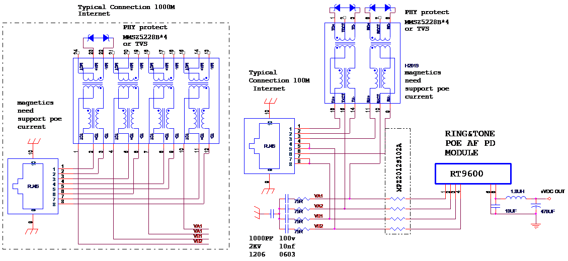
The RT9600 series of modules are designed to extract power from a conventional twisted pair Category 5 Ethernet cable, conforming to the IEEE 802.3af Power-over-Ethernet(PoE) standard.
The RT9600 signature and control circuit provides the PoE compatibility signature and
power classification required by the Power Sourcing Equipment (PSE) before applying up
to 15W power to the port. The RT9600 provides a Class 0 signature.
The DC/DC converter operates over a wide input voltage range and provides a regulated
output. The DC/DC converter also has built-in short-circuit output protection.
Related products
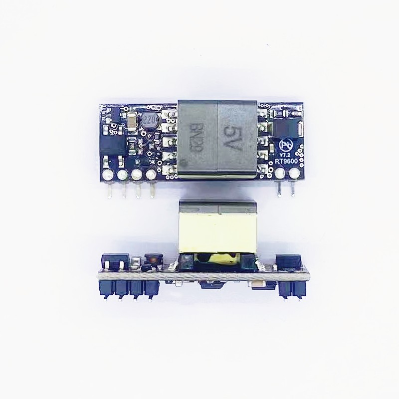
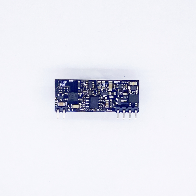
RT9600
12W POE PD Module ( Isolation Model)
Product Description
Version
Date
Author
Approved By
Remarks
V1.0
2013/10/14
LI xiao yan
Rock
V4.3
2014/12/01
LI xiao yan
Rock
© 2012 Shenzhen Ring&tone Electronic Technology Co., Ltd. All rights reserved.
This document contains proprietary information of ring&tone and is not to be disclosed or used without the prior written permission of ring&tone.
Due to update and improvement of ring&tone products and technologies, information in this document is subjected to change without notice.
Features:
Applications:
Description:
The RT9600 series of modules are designed to extract power from a conventional twisted pair Category 5 Ethernet cable, conforming to the IEEE 802.3af Power-over-Ethernet(PoE) standard.
The RT9600 signature and control circuit provides the PoE compatibility signature and
power classification required by the Power Sourcing Equipment (PSE) before applying up
to 15W power to the port. The RT9600 provides a Class 0 signature.
The DC/DC converter operates over a wide input voltage range and provides a regulated
output. The DC/DC converter also has built-in short-circuit output protection.
Part Number
Nominal Output Voltage
Maximum Output Power*
Marking
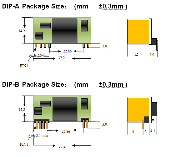
Package
RT9600-3.3V
3.3V
6.6W
3.3V
SIL
RT9600 -5V
5V
10W
5V
SIL
RT9600 -12V
12V
12W
12V
SIL
RT9600 -24V
24V
12W
24V
SIL
*At 25°C with VIN = 48V
Pin #
Name
Description
1
VA1
RX Input (1). This input pin is used in conjunction with VA2 and
connects to the centre tap of the transformer connected to pins 1
& 2 of the RJ45 connector (RX) - it is not polarity sensitive.
2
VA2
TX Input (2). This input pin is used in conjunction with VA1 and
connects to the centre tap of the transformer connected to pins 3
& 6 of the RJ45 connector (TX) - it is not polarity sensitive.
3
VB1
Direct Input (1). This input pin is used in conjunction with VB2 and connects to pin 4 & 5 of the RJ45 connector - it is not polarity
sensitive.
4
VB2
Direct Input (2). This input pin is used in conjunction with VB1 and connects to pin 7 & 8 of the RJ45 connector - it is not polarity
sensitive.
5
-VDC
DC Return. This pin is the return path for the +VDC output.
6
+VDC
DC Output. This pin provides the regulated output from the DC/DC converter.
Parameter
Symbol
Min
Max
Units
1
DC Supply Voltage
VCC
-0.3
60
V
2
DC Supply Voltage Surge for 1ms
VSURGE
-0.6
80
V
3
Storage Temperature
TS
-40
100
OC
Note 1: Exceeding the above ratings may cause permanent damage to the product. Functional operation under these conditions is not implied. Maximum ratings assume free airflow.
Parameter
Symbol
Min
Typ
Max
Units
Units
1
Input Supply Voltage1
VIN
36
48
57
V
V
2
Under Voltage Lockout
VLOCK
30
36
V
V
3
Operating Temperature2
TOP
-20
25
70
Ta / OC
RT9600
Note 1: With minimum load
2: See Section Operating Temperature Range
** Extended use close to, or at the maximum operating temperature can reduce the life time of the device.
DC Characteristic
Sym
Min
Typ1
Max
Units
Test Comments
1
Nominal Output Voltage
+VDC
3.1
4.75
11.5
23.5
3.3
5.0
12.0
24.0
3.5
5.25
12.5
24.5
V
V
V
V
RT9600-3.3V
RT9600-5V
RT9600-12V
RT9600-24V
2
Output Current (VIN = 48V)
PWR
2
2
1.0
0.5
A
A
A
A
3
Line Regulation
VLINE
0.1
%
@ 50% Load
4
Load Regulation
VLOAD
1
%
@ VIN=48V
5
Output Ripple and Noise
VRN
100
mVp-p
@ Max load2
6
Minimum Load
RLOAD
200
200
100
50
mA
mA
mA
MA
RT9600-3.3V
RT9600-5V
RT9600-12V
RT9600-24V
7
Short-Circuit Duration3
TSC
∞
sec
8
Efficiency @ 80% Load
EFF
79
84
87
87
%
%
%
%
RT9600-3.3V
RT9600-5V
RT9600-12V
RT9600-24V
9
Isolation Voltage (I/O)
VISO
1500
VPK
Impulse Test
10
Temperature Coefficient
TC
0.02
%
Per OC
Note 1: Typical figures are at 25°C with a nominal 48V supply and are for design aid only. Not Guaranteed
2: The output ripple and noise can be reduced with an external filter, see application note.
3: Continuous short circuit duration is applicable at 25'C ambient temperature in free air. At higher temperatures or with restricted
airflow (e.g. in a sealed enclosure) the duration will need to be limited to avoid overheating.